MỘTseries resonance (also known as variable frequency resonance) circuit is composed of a series capacitor and a capacitor, with an inductive coil L and a resistor R.
The ideal series resonant circuit consists only of an inductor (without its own resistance) and a capacitor (LC circuit). Then, in this system, the current in the circuit, the voltage across the capacitor, and the charge of the capacitor maintain continuous electromagnetic resonance. Let's take a look at the outline and consider the source of the vibration. Place the initially charged capacitor in the circuit we are describing.

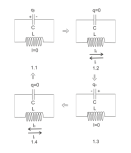
At the initial moment, all charges are concentrated on the capacitor and there is no current on the coil (Figure 1.1). Because there is no external electric field on the capacitor board, electrons from the board begin to "leave" into the circuit (the charge on the capacitor begins to decrease). In this case (due to the released electrons), the current in the circuit increases. In this case, the direction of the current is from positive to negative (but, as always), and the capacitor is the AC power source of the system. However, as the current on the coil increases, a reverse induced current (Ii) occurs due to electromagnetic induction. According to Lenz's law, the direction of the induced current should counteract (reduce) the increase in the main current. When the charge of the capacitor becomes zero (all charges will be depleted), the induced current intensity in the coil will reach its maximum value (Figure 1.2).
However, the current charge in the circuit cannot disappear (the law of conservation of charge), and then this charge leaves one electrode in the circuit and ultimately terminates on the other electrode. Therefore, the capacitor charges in the opposite direction (Figure 1.3). The induced current on the coil decreases to zero because the change in magnetic flux also tends towards zero.
When the capacitor is fully charged, electrons begin to move in the opposite direction, that is, the capacitor discharges in the opposite direction and generates current. When the capacitor is completely discharged, the current reaches its maximum value (Figure 1.4).
Further reverse charging of the capacitor causes the system to reach the position shown in Figure 1.1. As long as you are willing, this behavior of the system will repeat. Therefore, we obtained fluctuations in various parameters of the system: current in the coil, charge on the capacitor, and voltage on the capacitor. In ideal conditions of circuits and wires (without inherent resistance), these vibrations are harmonics.
In order to mathematically describe these parameters of the system (first the period of electromagnetic resonance), we introduced the Thomson formula we previously calculated:
There is only one small component: the presence of resistance R (LCR circuit). This resistor can be the resistance of a coil (not ideal) or the resistance of a wire. The general logic of resonance in non ideal circuits is similar to that in ideal circuits. The only difference lies in the resonance itself. If there is resistance, some of the energy will dissipate into the environment and the resistance will heat up. Then, the energy of the series resonant circuit will decrease, and the resonance itself will be attenuated.


